Practical Reverse Engineering Part 4 - Dumping the Flash
08 Jun 2016- Part 1: Hunting for Debug Ports
- Part 2: Scouting the Firmware
- Part 3: Following the Data
- Part 4: Dumping the Flash
- Part 5: Digging Through the Firmware
In Parts 1 to 3 we’ve been gathering data within its context. We could sniff the specific pieces of data we were interested in, or observe the resources used by each process. On the other hand, they had some serious limitations; we didn’t have access to ALL the data, and we had to deal with very minimal tools… And what if we had not been able to find a serial port on the PCB? What if we had but it didn’t use default credentials?
In this post we’re gonna get the data straight from the source, sacrificing context in favour of absolute access. We’re gonna dump the data from the Flash IC and decompress it so it’s usable. This method doesn’t require expensive equipment and is independent of everything we’ve done until now. An external Flash IC with a public datasheet is a reverser’s great ally.
Dumping the Memory Contents
As discussed in Part 3, we’ve got access to the datasheet for the Flash IC, so there’s no need to reverse its pinout:
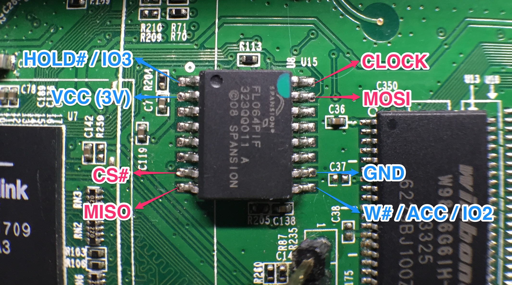
We also have its instruction set, so we can communicate with the IC using almost any device capable of ‘speaking’ SPI.
We also know that powering up the router will cause the Ralink to start communicating with the Flash IC, which would interfere with our own attempts to read the data. We need to stop the communication between the Ralink and the Flash IC, but the best way to do that depends on the design of the circuit we’re working with.
Do We Need to Desolder The Flash IC? [Theory]
The perfect way to avoid interference would be to simply desolder the Flash IC so it’s completely isolated from the rest of the circuit. It gives us absolute control and removes all possible sources of interference. Unfortunately, it also requires additional equipment, experience and time, so let’s see if we can avoid it.
The second option would be to find a way of keeping the Ralink inactive while
everything else around it stays in standby. Microcontrollers often have a Reset
pin that will force them to shut down when pulled to 0; they’re commonly used
to force IC reboots without interrupting power to the board. In this case we
don’t have access to the Ralink’s full datasheet (it’s probably distributed only
to customers and under NDA); the IC’s form factor and the complexity of the
circuit around it make for a very hard pinout to reverse, so let’s keep
thinking…
What about powering one IC up but not the other? We can try applying voltage directly to the power pins of the Flash IC instead of powering up the whole circuit. Injecting power into the PCB in a way it wasn’t designed for could blow something up; we could reverse engineer the power circuit, but that’s tedious work. This router is cheap and widely available, so I took the ‘fuck it’ approach. The voltage required, according to the datasheet, is 3V; I’m just gonna apply power directly to the Flash IC and see what happens. It may power up the Ralink too, but it’s worth a try.
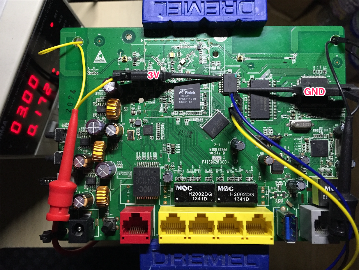
We start supplying power while observing the board and waiting for data from the Ralink’s UART port. We can see some LEDs light up at the back of the PCB, but there’s no data coming out of the UART port; the Ralink must not be running. Even though the Ralink is off, its connection to the Flash IC may still interfere with our traffic because of multiple design factors in both power circuit and the silicon. It’s important to keep that possibility in mind in case we see anything dodgy later on; if that was to happen we’d have to desolder the Flash IC (or just its data pins) to physically disconnect it from everything else.
The LEDs and other static components can’t communicate with the Flash IC, so they won’t be an issue as long as we can supply enough current for all of them. I’m just gonna use a bench power supply, with plenty of current available for everything. If you don’t have one you can try using the Master’s power lines, or some USB power adapter if you need some more current. They’ll probably do just fine.
Time to connect our SPI Master.
Connecting to the Flash IC
Now that we’ve confirmed there’s no need to desolder the Ralink we can connect
any device that speaks SPI and start reading memory contents block by block.
Any microcontroller will do, but a purpose-specific SPI-USB bridge will often
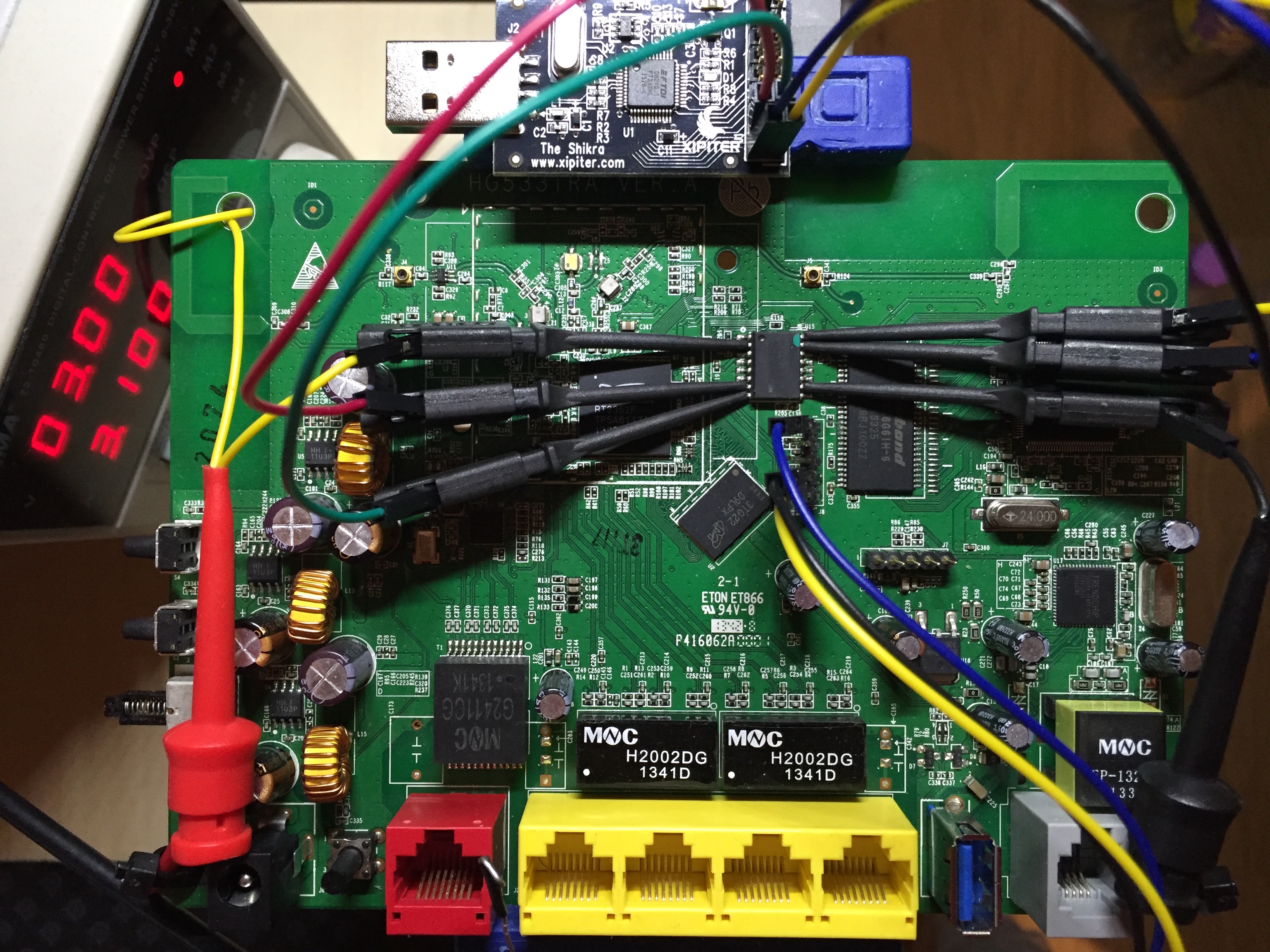
be much faster. In this case I’m gonna be using a board based on the FT232H,
which supports SPI among some other low level protocols.
We’ve got the pinout for both the Flash and my USB-SPI bridge, so let’s get everything connected.
Now that the hardware is ready it’s time to start pumping data out.
Dumping the Data
We need some software in our computer that can understand the USB-SPI bridge’s traffic and replicate the memory contents as a binary file. Writing our own wouldn’t be difficult, but there are programs out there that already support lots of common Masters and Flash ICs. Let’s try the widely known and open source flashrom.
flashrom is old and buggy, but it already supports both the FT232H as
Master and the FL064PIF as Slave. It gave me lots of trouble in both OSX and
an Ubuntu VM, but ended up working just fine on a Raspberry Pi (Raspbian):
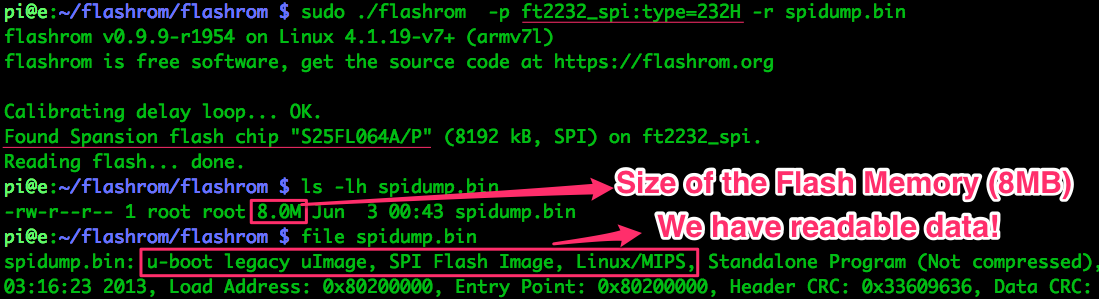
Success! We’ve got our memory dump, so we can ditch the hardware and start preparing the data for analysis.
Splitting the Binary
The file command has been able to identify some data about the binary, but
that’s just because it starts with a header in a supported format. In a
0-knowledge scenario we’d use binwalk
to take a first look at the binary file and find the data we’d like to extract.
Binwalk is a very useful tool for binary analysis created by the awesome hackers at /dev/ttyS0; you’ll certainly get to know them if you’re into hardware hacking.
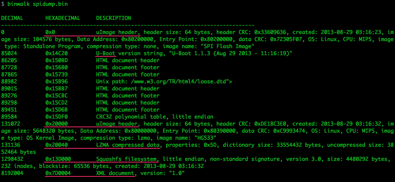
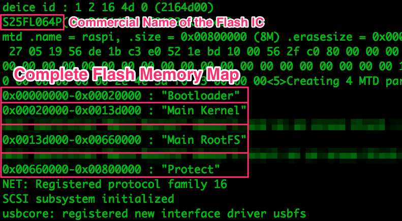
In this case we’re not in a 0-knowledge scenario; we’ve been gathering data since day 1, and we obtained a complete memory map of the Flash IC in Part 2. The addresses mentioned in the debug message are confirmed by binwalk, and it makes for much cleaner splitting of the binary, so let’s use it:
With the binary and the relevant addresses, it’s time to split the binary into
its 4 basic segments. dd takes its parameters in terms of block size (bs,
bytes), offset (skip, blocks) and size (count, blocks); all of them in
decimal. We can use a calculator or let the shell do the hex do decimal
conversions with $(()):
$ dd if=spidump.bin of=bootloader.bin bs=1 count=$((0x020000))
    131072+0 records in
    131072+0 records out
    131072 bytes transferred in 0.215768 secs (607467 bytes/sec)
$ dd if=spidump.bin of=mainkernel.bin bs=1 count=$((0x13D000-0x020000)) skip=$((0x020000))
    1167360+0 records in
    1167360+0 records out
    1167360 bytes transferred in 1.900925 secs (614101 bytes/sec)
$ dd if=spidump.bin of=mainrootfs.bin bs=1 count=$((0x660000-0x13D000)) skip=$((0x13D000))
    5386240+0 records in
    5386240+0 records out
    5386240 bytes transferred in 9.163635 secs (587784 bytes/sec)
$ dd if=spidump.bin of=protect.bin bs=1 count=$((0x800000-0x660000)) skip=$((0x660000))
    1703936+0 records in
    1703936+0 records out
    1703936 bytes transferred in 2.743594 secs (621060 bytes/sec)
We have created 4 different binary files:
bootloader.bin: U-boot. The bootloader. It’s not compressed because the Ralink wouldn’t know how to decompress it.mainkernel.bin: Linux Kernel. The basic firmware in charge of controlling the bare metal. Compressed usinglzmamainrootfs.bin: Filesystem. Contains all sorts of important binaries and configuration files. Compressed assquashfsusing thelzmaalgorithmprotect.bin: Miscellaneous data as explained in Part 3. Not compressed
Extracting the Data
Now that we’ve split the binary into its 4 basic segments, let’s take a closer look at each of them.
Bootloader
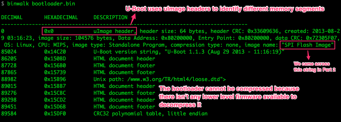
Binwalk found the uImage header and decoded it for us. U-Boot uses these headers
to identify relevant memory areas. It’s the same info that the file command
displayed when we fed it the whole memory dump because it’s the first header in
the file.
We don’t care much for the bootloader’s contents in this case, so let’s ignore it.
Kernel
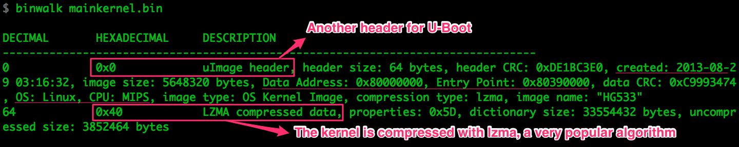
Compression is something we have to deal with before we can make any use of the
data. binwalk has confirmed what we discovered in Part 2, the kernel
is compressed using lzma, a very popular compression algorithm in embedded
systems. A quick check with strings mainkernel.bin | less confirms there’s no
human readable data in the binary, as expected.
There are multiple tools that can decompress lzma, such as 7z or
xz. None of those liked mainkernel.bin:
$ xz --decompress mainkernel.bin
xz: mainkernel.bin: File format not recognized
The uImage header is probably messing with tools, so we’re gonna have to strip
it out. We know the lzma data starts at byte 0x40, so let’s copy everything
but the first 64 bytes.
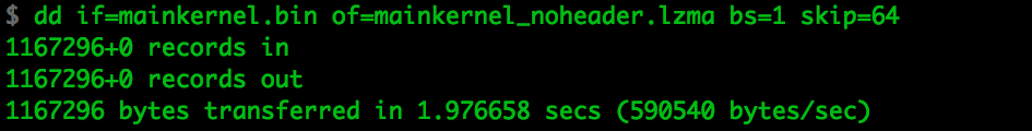
And when we try to decompress…
$ xz --decompress mainkernel_noheader.lzma
xz: mainkernel_noheader.lzma: Compressed data is corrupt
xz has been able to recognize the file as lzma, but now it doesn’t like the
data itself. We’re trying to decompress the whole mainkernel Flash area, but
the stored data is extremely unlikely to be occupying 100% of the memory segment.
Let’s remove any unused memory from the tail of the binary and try again:
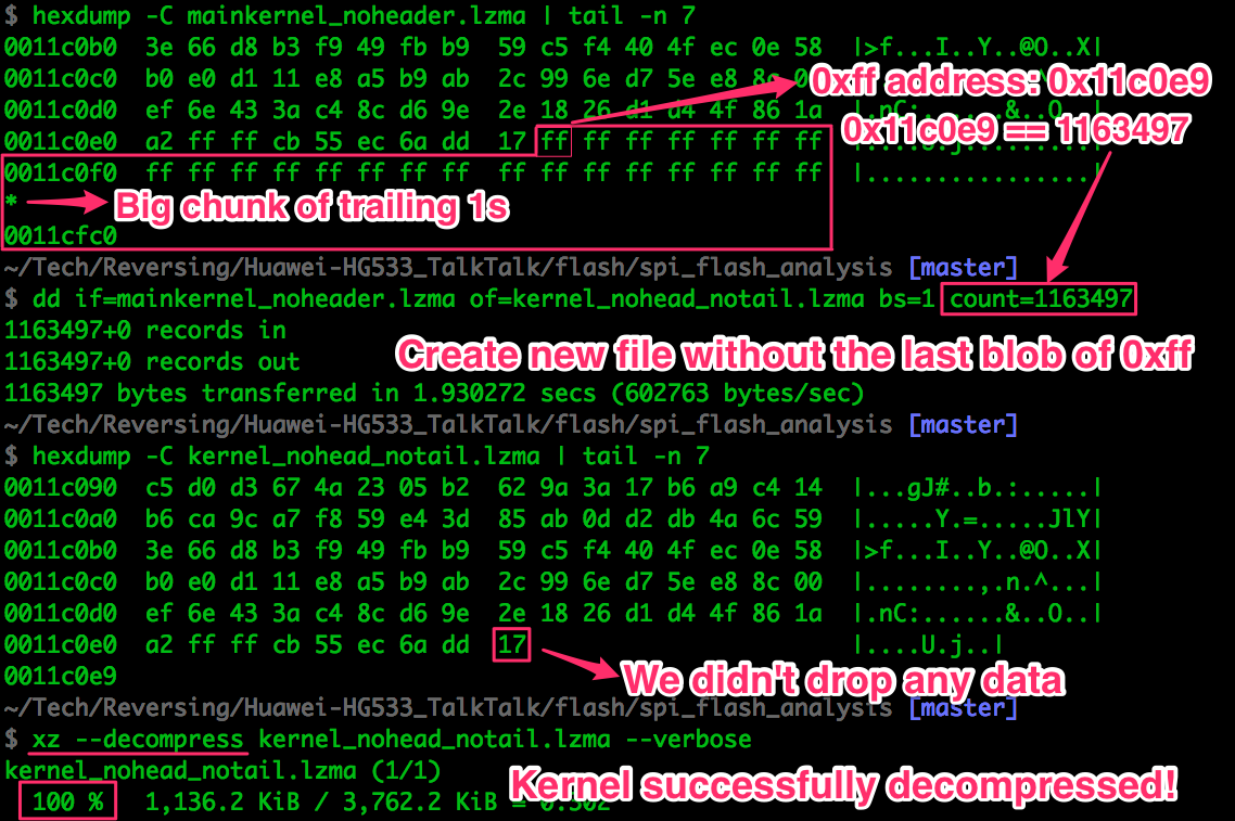
xz seems to have decompressed the data successfully. We can easily verify that
using the strings command, which finds ASCII strings in binary files. Since
we’re at it, we may as well look for something useful…
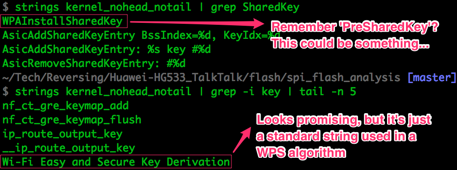
The Wi-Fi Easy and Secure Key Derivation string looks promising, but as it
turns out it’s just a hardcoded string defined by the
Wi-Fi Protected Setup spec.
Nothing to do with the password generation algorithm we’re interested in.
We’ve proven the data has been properly decompressed, so let’s keep moving.
Filesystem
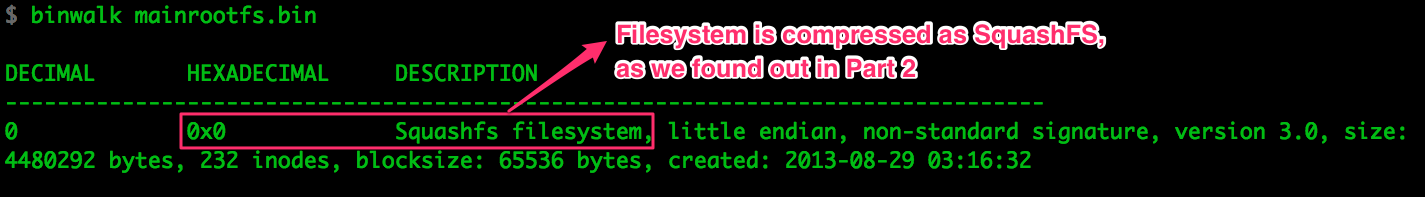
The mainrootfs memory segment does not have a uImage header because it’s
relevant to the kernel but not to U-Boot.
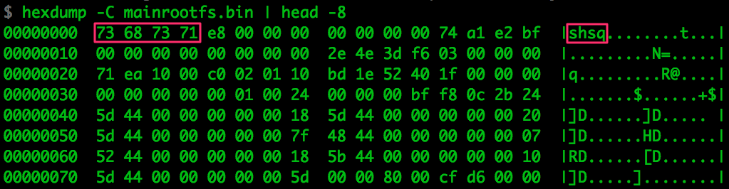
SquashFS is a very common filesystem in embedded systems. There are multiple
versions and variations, and manufacturers sometimes use custom signatures to
make the data harder to locate inside the binary. We may have to fiddle with
multiple versions of unsquashfs and/or modify the signatures, so let me show
you what the signature looks like in this case:
Since the filesystem is very common and finding the right configuration is
tedious work, somebody may have already written a script to automate the task.
I came across this
OSX-specific fork
of the
Firmware Modification Kit,
which compiles multiple versions of unsquashfs and includes a neat script
called unsquashfs_all.sh to run all of them. It’s worth a try.
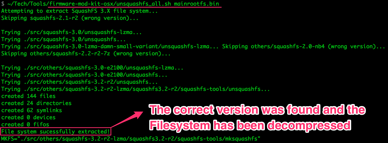
Wasn’t that easy? We got lucky with the SquashFS version and supported signature,
and unsquashfs_all.sh managed to decompress the filesystem. Now we’ve got
every binary in the filesystem, every symlink and configuration file, and
everything is nice and tidy:
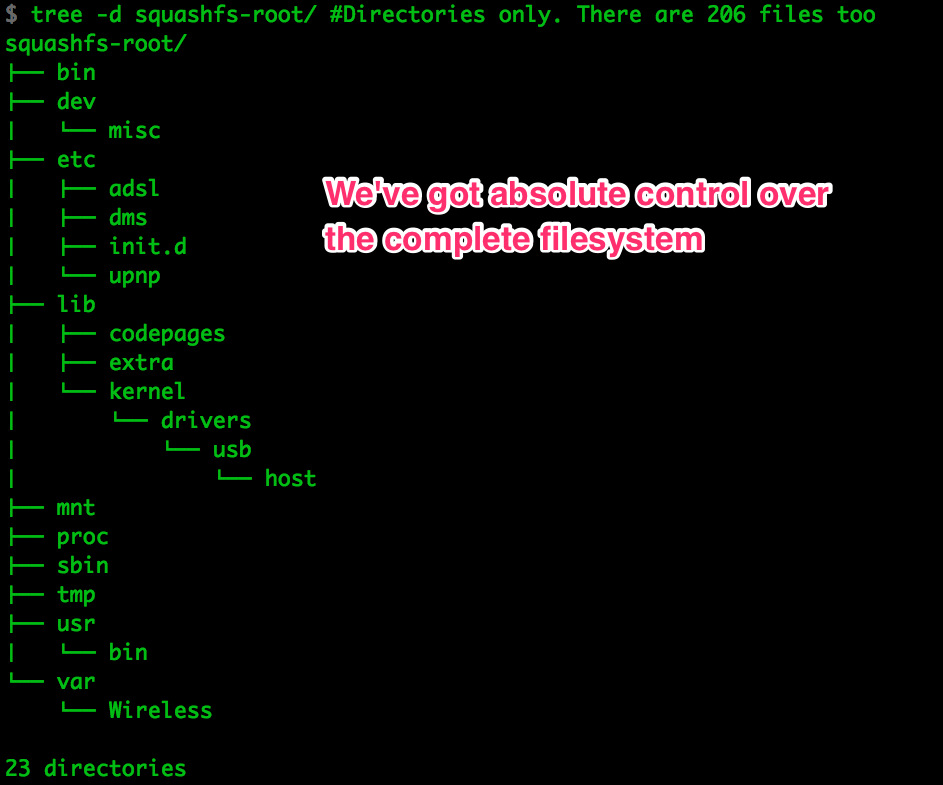
In the complete
file tree
we can see we’ve got every file in the system, (other than runtime files like
those in /var/, of course).
Using the intel we have been gathering on the firmware since day 1 we can start looking for potentially interesting binaries:
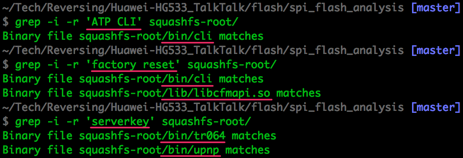
If we were looking for network/application vulnerabilities in the router, having every binary and config file in the system would be massively useful.
Protected
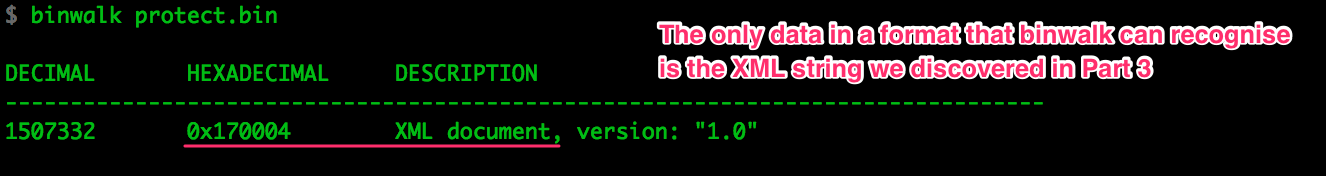
As we discussed in Part 3, this memory area is not compressed and contains all
pieces of data that need to survive across reboots but be different across
devices. strings seems like an appropriate tool for a quick overview of the
data:
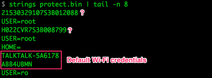
Everything in there
seems to be just the curcfg.xml contents, some logs and those few isolated
strings in the picture. We already sniffed and analysed all of that data in Part
3, so there’s nothing else to discuss here.
Next Steps
At this point all hardware reversing for the Ralink is complete and we’ve
collected everything there was to collect in ROM. Just think of what you may be
interested in and there has to be a way to find it. Imagine we wanted to control
the router through the UART debug port we found in Part 1, but when we try to
access the ATP CLI we can’t figure out the credentials. After dumping the
external Flash we’d be able to find the XML file in the protect area, and
discover the credentials just like we did in Part 2
(The Rambo Approach to Intel Gathering, admin:admin).
If you couldn’t dump the memory IC for any reason, the firmware upgrade files provided by the manufacturers will sometimes be complete memory segments; the device simply overwrites the relevant flash areas using code previously loaded to RAM. Downloading the file from the manufacturer would be the equivalent of dumping those segments from flash, so we just need to decompress them. They won’t have all the data, but it may be enough for your purposes.
Now that we’ve got the firmware we just need to think of anything we may be interested in and start looking for it through the data. In the next post we’ll dig a bit into different binaries and try to find more potentially useful data.